
OBD2 Pinout Diagram and What Each of the 16 Pins Does
-
01
OBD2 pin 16 delivers constant vehicle battery power, even with the ignition switch off.
-
02
Pin 4 is chassis ground and pin 5 is signal ground on every OBD2 connector.
-
03
Pins 6 and 14 carry controller area network data on US cars built since 2008.
-
04
The vehicle's manufacturer decides what pins 1, 3, 8, 9, 11, 12 and 13 do.
-
05
OBD2 has no standard ignition pin, so test any switched pin with a multimeter first.
OBD2 Port Pinout Explained for All 16 Pins (Color-Coded Diagram)
Figuring out the OBD2 pinout gets real when you're flat on your back under the dash, a flashlight in your teeth, with 16 tiny pins staring back at you. Which one carries battery power? Which one is ground? And why do the pin diagrams you find online seem to disagree?
After more than 15 years of installing GPS trackers in vehicles, I've learned that getting the pin positions right saves a lot of troubleshooting headaches. I also checked the power connections with a multimeter on my 2017 Nissan Pathfinder to verify the readings. In this guide, I'll walk you through all 16 OBD2 pins, explain their functions, and show you how to test the port before connecting a scanner or GPS tracker.
You'll get a color-coded diagram, a pin-by-pin reference table, and practical steps for checking power and ground. By the end, you'll have a clear reference to help you troubleshoot your OBD2 connection with confidence.
DISCLOSURE: As an Amazon Associate, Konnect GPS earns from qualifying purchases.
OBD2 Pinout Diagram For All 16 Pins
The OBD2 pinout is the SAE J1962 layout of the 16 pin data link connector under your dash. Pin 16 supplies vehicle battery power, pins 4 and 5 provide ground, pins 6 and 14 carry CAN data, and the vehicle's manufacturer controls pins 1, 3, 8, 9, 11, 12 and 13.

You'll find that socket near the steering wheel. The J1962 rules put the OBD2 connector on the instrument panel within reach of the driver's seat, no more than about a foot past the center of the car.
Hold the socket wide side up. Pins 1 to 8 run left to right across the top row, and pins 9 to 16 run along the bottom.
All 16 OBD2 Pins, Color Coded
- Pin 16 Battery powerConstant battery power, 12V on Type A sockets
- Pins 4 and 5 GroundChassis ground and signal ground
- Pins 6 and 14 CAN high and lowController area network on every US car since 2008
- Pins 7 and 15 K-Line and L-LineISO 9141-2 and Keyword Protocol 2000 data
- Pins 2 and 10 SAE J1850Ford PWM uses both pins, GM VPW uses pin 2
- Pins 1, 3, 8, 9, 11, 12, 13 Manufacturer pinsSet by the automaker and different from brand to brand
Probing the plug instead? The scan tool or tracker plug is a mirror image, so pin 1 sits top right and pin 16 sits bottom left.
I see one mix-up more than any other. Your car carries the female socket, while your diagnostic scan tool or a tracker's adapter cable carries the male plug. Turn that plug around to read its face and the numbers run backwards, so pin 1 lands on the top right instead of the top left.
Probe the mirror side by mistake and you'll be hunting for 12 volts on a ground pin. The table below runs all 16 pins left to right.
| Pin | 1 | 2 | 3 | 4 | 5 | 6 | 7 | 8 | 9 | 10 | 11 | 12 | 13 | 14 | 15 | 16 |
|---|---|---|---|---|---|---|---|---|---|---|---|---|---|---|---|---|
| Name | Manufacturer | J1850 Bus+ | Manufacturer | Chassis Ground | Signal Ground | CAN High | K Line | Manufacturer | Manufacturer | J1850 Bus- | Manufacturer | Manufacturer | Manufacturer | CAN Low | L Line | Battery Power |
| What It Does | Varies by make, sometimes switched ignition power | Ford PWM and General Motors VPW data | Varies by make | Grounds devices to the car body | Clean ground for data lines | CAN high line, ISO 15765-4 | ISO 9141-2 and 14230-4 data | Varies by make | Varies by make | Ford PWM data only | Varies by make | Varies by make | Varies by make | CAN low line, ISO 15765-4 | Optional wake-up line | Constant battery power, 12V on Type A |
| Set By | Automaker | SAE J1962 | Automaker | SAE J1962 | SAE J1962 | SAE J1962 | SAE J1962 | Automaker | Automaker | SAE J1962 | Automaker | Automaker | Automaker | SAE J1962 | SAE J1962 | SAE J1962 |
Nine pins have jobs fixed by the standard, and the other pins belong to the vehicle's manufacturer. Power and ground come next, since every scan tool and tracker you plug in leans on them.
OBD2 Connector Power And Ground Pins
The OBD2 connector gets its power from pin 16 and its ground from pins 4 and 5. Pin 16 carries constant vehicle battery power, pin 4 is chassis ground, and pin 5 is signal ground for the data lines. Those three pins power every scan tool, dash cam cable and GPS tracker you plug in.
Pin 16 never sleeps. Turn the key off, pull it out, walk inside, and pin 16 still carries battery voltage.

I checked this myself on my 2017 Nissan Pathfinder here in Southern California. With the key out of the ignition switch, my meter showed full battery voltage between pin 16 and pin 4.
Each of these three pins has its own job, and mixing them up is where most wiring headaches start.
- Pin 16 Battery Power: Constant 12-volt battery power on Type A sockets, live with the ignition switch off on most cars.
- Pin 4 Chassis Ground: Ties your device to the car's metal body and completes the power circuit from pin 16.
- Pin 5 Signal Ground: A cleaner ground reference that keeps electrical noise away from the data lines and readings.
Automotive engineers split the grounds on purpose, because motors, fans and ignition coils dump electrical noise onto the chassis. A separate signal ground gives the electronic control unit and your scan tool a steadier reference for normal communication.
Heads-up on modern vehicles, though. Some newer models manage pin 16 power after a long stretch parked to save the battery.
Pin 16 is also why a plug-in GPS tracker for car use never needs charging. The Konnect OBD2 GPS Tracker uses pin 16 as its power source and pulls location from its own GPS chip, instead of polling the electronic control unit all day. I like that setup because the tracker leaves the car's electronics alone. Yank the tracker out of the socket and you get a tamper alert, plus about 15 minutes of backup reporting from its small internal battery.
Constant power raises the next question everyone asks, which pin switches on with the key?
OBD II Ignition Pin And Switched Power
The OBD II connector has no standard ignition pin, because SAE J1962 never assigns switched power to any of its 16 pins. Pin 16 stays hot with the key on or off, and some automakers put switched ignition power on a manufacturer pin such as 1 or 8.

Finding a switched pin on your own car takes about two minutes with a multimeter.
- Set the meter to DC volts.
- Clip the black lead to pin 4.
- Touch each manufacturer pin with the key off.
- Repeat with the ignition switch turned on.
A pin that reads zero with the key off and full battery voltage with the key on is your switched pin.
Dash cam owners learn this the hard way. OBD power cables can't see an ignition signal, so the adapters guess when to drop into parking mode, and some nights your camera records an empty driveway until morning. Any device left in the port has the same job, managing its own power while your car sits parked.
RELATED READING Does An OBD GPS Tracker Drain Your Car Battery? Pin 16 stays live overnight, so here is what a plugged-in tracker really draws while the car sits parked. See the real drawPower and ignition cover the electrical side of the socket. The data pins handle the actual conversation between your car and the scan tool.
OBD2 Data Pins For CAN, J1850 And K-Line
The OBD2 data pins are 6 and 14 for the controller area network, 2 and 10 for SAE J1850, and 7 and 15 for the K line and L line. Your car talks to a scan tool over one of these pin sets, and the sections below break down each communication protocol.
Think of the pins as phone lines and the protocol as the language spoken on them.
1. Controller Area Network On Pins 6 And 14

Pin 6 is the CAN high pin and pin 14 is the CAN low pin, forming the two-wire controller area network every US car has used for OBD2 since 2008. The International Organization for Standardization wrote the bus rules as ISO 15765-4, and most cars run it at 500 kbps with 11-bit IDs.
Two details explain why CAN won the job.
- Both wires carry mirror-image signals, so electrical noise cancels itself out.
- Many independent controllers share one bus without a separate wire for each.
My 2017 Pathfinder talks CAN on these two pins like every other post-2008 car.
2. Pulse Width Modulation And General Motors VPW

Pin 2 is the SAE J1850 bus positive pin and pin 10 is the bus negative pin, the data lines older Ford vehicles and General Motors vehicles used before CAN took over.
Ford runs pulse width modulation, a square wave sent across both pins as a matched pair at 41.6 kbps. General Motors went with variable pulse width instead, so the VPW bus operates on pin 2 alone at 10.4 kbps.
An empty pin 10 on an older Chevy or GMC truck is normal, not a broken socket.
RELATED READING SAE J1850 Protocol, VPW vs PWM Explained How Ford PWM and GM VPW split pins 2 and 10, and which one your older truck actually speaks. Decode J18503. K-Line And L-Line On Pins 7 And 15

Pin 7 is the K line, a single wire that carries ISO 9141-2 and ISO 14230-4, also known as Keyword Protocol 2000. Both run an asynchronous serial communication protocol, one bit at a time down a single line pin. Pin 15, the L line, only helps wake the system on some cars.
Three facts help when you're staring at an older import.
- ISO 9141-2 showed up on European, Chrysler and Asian cars from 2000 to 2004.
- Keyword Protocol 2000 became common on many Asian cars from around 2003 onward.
- Both share pins 7 and 15, so the socket alone can't tell them apart.
A scan tool sorts that out in seconds.
4. Diagnostic Trouble Codes And Parameter IDs
Diagnostic trouble codes and parameter IDs are what actually travel across those data pins. A DTC like P0420 is a fault the electronic control unit has stored, while a PID is a live reading such as vehicle speed, engine RPM or coolant temperature.
The OBD2 standard defines around 200 live-data PIDs, yet most 2008 and newer non-electric cars only answer 40 to 80 of them. The engine computer, transmission control module and other modules each answer with whatever they support. The same reporting system powers remote vehicle diagnostics in fleet software and insurance dongles.
The pins your car actually uses give away its protocol, which decides what a scanner or tracker can read. Seven pins are still unaccounted for, and those belong to the automaker.
RELATED READING What Are The OBD2 Protocols & GPS Tracker Compatibility Match your car's protocol to the right scanner or tracker before you spend money on either. Find your protocolManufacturer Pins In The Connector Pinout
Pins 1, 3, 8, 9, 11, 12 and 13 are the manufacturer pins in the OBD2 connector pinout. SAE J1962 leaves these other pins to the vehicle's manufacturer, so the same pin can do a different job from one brand to the next, or sit empty.

Not every pin is even populated, so expect a few empty slots.
Automakers use these pins across various subsystems, for switched ignition control, extra CAN networks for infotainment, dealer programming lines and brand-specific airbag or ABS diagnostics.
Finding your exact layout takes a little homework, and these five sources do the job best.
- The factory service manual for your exact model year.
- Manufacturer-specific wiring diagrams for the diagnostic connector circuit.
- Repair databases like ALLDATA, which some public libraries offer.
- Owner forums and pinout databases, cross-checked against each other.
- The key-on, key-off meter test from the ignition section.
I always trust the factory manual over any forum chart.
Some electric cars skip the standard socket altogether. The Tesla Model 3 and Model Y need a brand-specific adapter before a scan tool can connect.
Never assume a manufacturer pin does the same job across makes. Jumping or tapping the wrong pin can blow a fuse or damage a module, so test before you connect anything.
Pin jobs vary by brand, but the plug itself comes in two shapes.
Type A vs Type B OBD2 Connectors
Type A OBD2 connectors deliver 12 volts and sit in cars and light trucks, while Type B connectors deliver 24 volts for medium and heavy vehicles. Both share the same 16 pin OBD2 connector layout, so the OBD2 pinout you just learned works on either one.

The differences show up in the plastic and the power, and the table lays them side by side.
| Feature | Type A | Type B |
|---|---|---|
| Pin 16 voltage | 12 volts | 24 volts |
| Center groove | Solid | Interrupted in the middle |
| Front marking | None | Blue |
| Common CAN speed | 500 kbps | 250 kbps, newer trucks 500 kbps |
| Typical vehicles | Cars and light trucks | Medium and heavy-duty vehicles |
| Plug fit | Takes Type A and Type B plugs | Takes Type B plugs only |
The groove does the safety work. A Type B adapter cable plugs into either socket, but a Type A plug won't seat in a Type B socket, which keeps a 12-volt scan tool off a 24-volt truck.
Your car or pickup almost certainly has Type A, since US OBD rules cap the connector at 20 volts on the vehicles they cover.
Many heavy trucks skip the 16-pin socket for a round 9-pin J1939 connector.
One more catch on older cars. A 16-pin socket on a pre-1996 model doesn't guarantee OBD II compliance, because some automakers fitted the plug before the full system arrived.
Next comes proof the port actually works.
Test Your OBD2 Port With A Multimeter
You can test an OBD2 port in about a minute with a basic multimeter. Check for battery voltage between pins 16 and 4, then check for about 60 ohms across pins 6 and 14, the two CAN pins.

Grab the meter and a flashlight, and check the OBD2 port pinout in this order.
- Set your multimeter to DC volts and switch the ignition off.
- Touch the black lead to pin 4 and the red lead to pin 16.
- Look for about 12.4 to 12.7 volts, the normal resting battery voltage.
- Move the black lead to pin 5 and confirm the same reading.
- Disconnect the negative battery cable and switch the meter to ohms.
- Touch the leads to pins 6 and 14 and look for about 60 ohms.
See 60 ohms? Yup, your CAN bus wiring is healthy. Near 120 ohms usually means a missing or open termination resistor, near zero points to a shorted pair, and no reading means an open circuit.
Two 120-ohm termination resistors sit at the ends of the CAN bus, and wired in parallel they read 60 ohms across pins 6 and 14.
Source: YOUCANIC, OBD2 Port.
I ran this same check on my 2017 Nissan Pathfinder here in Southern California, and finding the port with a flashlight took longer than the test itself. Pin 16 showed full battery voltage with the key out.
No Power At Pin 16
A blown fuse is the usual reason pin 16 shows no battery voltage. On a lot of cars the OBD2 port shares a fuse with the cigarette lighter or power outlet, so a dead phone charger socket is a strong clue. Check the fuse chart in your owner's manual, swap in a fuse of the same rating, and test again.

Test pin 4 against a bare metal bolt next if pin 16 looks fine but your scanner still won't power up, since a broken ground kills power just as fast.
RELATED READING OBD Port Not Working A dead port is usually a blown fuse. Run the checks in the same order a mechanic would. Fix the portNever bridge pins with a paperclip or short pin 16 to ground. Skip fat probe tips too, because they spread the terminals and leave you with a loose connection on every plug that follows. Thin back-probe pins or an OBD2 breakout box keep the socket safe.
With power, ground and the bus checked, the last question is what your plug-in device does with all of it.
OBD2 Pins For Your Plug-In Device Uses
Every OBD2 plug-in device draws power from pin 16 and ground from pins 4 and 5, and some also talk on the data pins. The table shows which pins each common device actually uses.

| Device | Scan Tool | Dash Cam OBD Cable | Insurance Dongle | GPS Tracker |
|---|---|---|---|---|
| Pins used | 16, 4, 5 and the data pins | 16, 4 and 5 | 16, 4, 5 and the data pins | 16, 4 and 5, data use varies by brand |
| Reads car data | Yes, codes and live data | No | Yes, driving data | Varies by brand |
| Stays plugged in | Only while you scan | Yes | Yes | Yes |
Two warnings before you stack devices. Cheap splitters can bridge pins that should never touch. GM's own service bulletin also warns that aftermarket devices on the port, including insurance tracking devices, can block the built-in OnStar diagnostics on older GM models.
RELATED READING What Is An OBD2 Port? A Simple Guide For Drivers New to the socket? The plain-English guide covers what the port does and why every device leans on it. Start with the basicsBefore you plug anything into the OBD2 port, check how much power it draws from pin 16 while the car sits parked.
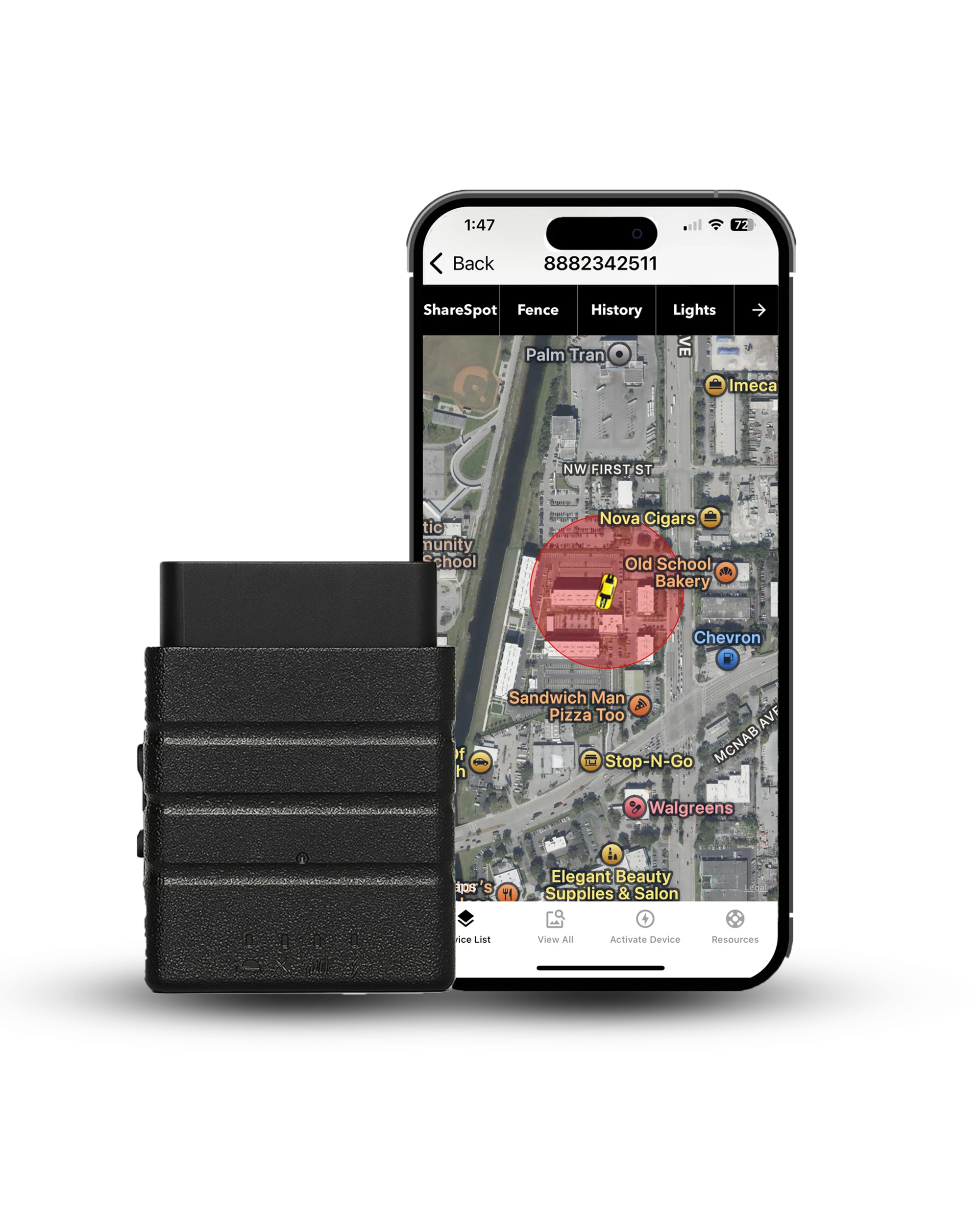
Konnect keeps the job simple. The tracker takes power from pin 16, finds the car with its own GPS chip, and skips constant engine polling, so the electrical load on your vehicle stays light.

- Live location every 3 seconds, where most trackers update once a minute
- Speed, geofence and tamper alerts on iPhone and Android
- A full year of trip history
- Lifetime warranty and free US shipping
Every pin on the socket is covered now, so let's wrap it up.
Conclusion
The OBD2 pinout comes down to four groups. Pin 16 brings constant battery power, pins 4 and 5 handle ground, one data pair carries your car's protocol, and seven manufacturer pins do whatever the automaker decides.
Keep this OBD2 pin diagram handy and most wiring mysteries under the dash solve themselves.
I've spent more than 15 years plugging trackers and scan tools into these sockets, and the habit that saves the most headaches is simple. Run the one-minute meter test before you plug anything in, and you'll know the port is healthy before you blame the device.
Pin 16 never sleeps, so pick devices that let your battery rest.
Sources
- SAE J1962 Diagnostic Connector
- ISO 15765-4, Diagnostic communication over CAN
- CSS Electronics, OBD2 Explained
- YOUCANIC, OBD2 Port
- GM service bulletin hosted by NHTSA

Konnect plugs into the port under your dash in seconds, draws power from pin 16, and shows your car's location every 3 seconds. You get speed, geofence and tamper alerts, a full year of trip history and a lifetime warranty for $39.95 plus $8.95 a month. Cancel anytime.
Free US shipping, 30-day money-back guarantee
DISCLOSURE: As an Amazon Associate, Konnect GPS earns from qualifying purchases.
About the Author

 Buy on Amazon